
Navigation
Installation Instructions

Proper Operation of the J1939 Converter Box is dependant on correct installation of the devices involved. Please follow these instructions exactly in order to assure a quick and easy setup.
Before proceeding with installation of the Converter Box the OmniTRACS system must be properly installed and set up on the vehicle.
Refer to the Qualcomm Installation and Diagnostic Guides for further information on completing the OmniTRACS installation.
J1939 Converter Box Hardware Installation:
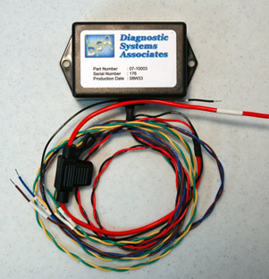
Installation of the Translator module will require mounting the module and connecting the following wires:
- IGNITION
- GROUND
- J1939 + (CAN HIGH)
- J1939 - (CAN LOW)
- QCOM J1708 +
- QCOM J1708 -
Converter Location and Mounting:
- Identify a location in the vehicle cab where the converter can be fastened tightly and is near the necessary power and communications wiring. Most often, a location near the center of the dashboard is ideal.
- Secure the converter to the vehicle with screws or zip-ties through the two mounting tabs to insure it does not move or vibrate excessively during vehicle operation. Do not mount the converter or run wires in the path of heater outlets or in any location where it may interfere with vehicle control mechanisms or damage the unit. Keep away from brake pedals, etc.
Vehicle J1939 Bus Connections:
It is very important that the connections to the vehicle J1939 Bus be done properly and at an appropriate location to prevent problems with vehicle communications. Improper connections to the J1939 Bus can result in vehicle operational and/or safety problems. Always refer to the vehicle manufacturer’s specific instructions for connecting to the J1939 network.
Connections to the J1939 Bus should only be made at designated “stub” connection points. Some manufacturers provide accessory connections that can be used by the converter box. Refer to the specific vehicle service information for the presence of and locations of these connection points on the vehicle.
Determine a suitable J1939 location point. In many vehicles you can connect behind the truck diagnostic connector. Be aware that only one electronic device should be connected to the J1939 stub at the back of the diagnostic connector at a time. If another device is already present you will need to splice directly into the vehicle's J1939 backbone.
IMPORTANT: There should only be one device connected at this location at any time.
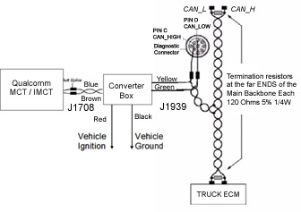
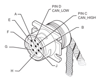
Pin “C” in this connector contains the CAN + Circuit (Yellow Wire) and Pin “D” contains the CAN – Circuit (Green Wire).
WARNING: Do not extend J1939 factory wires, maximum stub length is 10 feet, Minimum stub spacing is 4 inches and never have more than one ECM device on the same stub.
Follow the steps below to connect to the CAN Bus at the Diagnostic Connector:
- Start the vehicle and verify that the truck is in good working order and displays no dash faults.
- Turn OFF the truck and ensure that no dash lights are on.
Note: Some trucks may have activity on the J1939 bus with the door open or if an accessory is active. This can cause a faulty resistance reading on the CAN bus.
- Measure the J1939 bus resistance at the diagnostic connector. It should read between 55 to 65 ohms. Using an ohmmeter, place the positive lead on pin C and the negative lead on pin D of the diagnostic connector. Verify that the resistance is 55–65 ohms.
Note: If the test failed, you have a problem with your J1939 data bus. Stop and resolve this problem before proceeding.
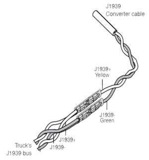
- Locate the Yellow/Green Twisted Pair wires approximately 2-inches back from the diagnostic connector, (remove the outer casing of the twisted pair if necessary to expose more of the wires). Refer to Vehicle J1939 Bus Connections earlier in this document.
- Cut the Yellow and Green wires at the proper location and strip approximately ¼ inch of the wire insulation on these wires.
- Splice the yellow CAN high J1939+ wire from the converter cable to the yellow CAN high J1939+ wire from the truck’s J1939 bus.
- Splice the green CAN low J1939- wire from the converter cable to the green CAN low J1939- wire from the truck’s J1939 bus.
- Measure the J1939 bus resistance at the diagnostic connector. It should read between 55 to 65 ohms.
If the test failed, double-check the connections and wiring. This problem must be resolved before proceeding.
OmniTRACS Connections:
Using the included butt-splices, connect the J1708 communications wires from the Converter Box to the J1708 wires on the OmniTRACS harness. Follow the same procedure as shown above for the J1939 connections.
- The Brown J1708 + wire should connect to the Brown J1708 + wire on the OmniTRACS harness.
- The Blue J1708 - wire should connect to the Red J1708 - wire on the OmniTRACS unit.
Power Connections:
The converter 12-Volt power connection (Red Wire) must be made to a fused, switched-ignition power source. This connection should be made in the vehicle electrical center at an accessory power connection terminal provided by the manufacturer for this purpose.
It is important that the device is connected to Switched Ignition Power ONLY and not constant battery power or it will not function properly.
The converter ground connection (Black wire) should be connected to vehicle chassis ground.
System Verification
SensorTRACS Verification:
Once all the connections have been made, the Converter Box installation is complete. To verify the connections:
- Using the OmniTRACS display unit, access the J1708 Installer screen within the SensorTRACS application screens, (refer to the OmniTRACS installation manual).
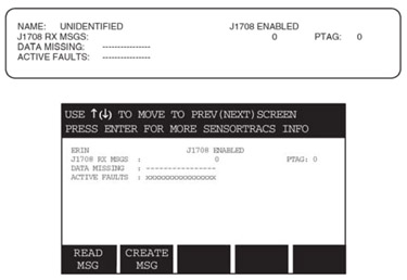
- Check the J1708 RX MSGS field value. This value should be a constantly increasing number when the engine is running. If the number is rapidly increasing, you are receiving J1708 messages. If the number is not rapidly increasing, you are not receiving J1708 messages, and you need to recheck the installation.
- Check the DATA MISSING field value with the key ON. If this value shows 012345678, (this indicates there is no data is being received) there a problem with the device or installation and corrective action must be taken.
If data is present in most fields (indicated by a “-“) you are receiving J1708 data (example “------67-“) and the installation is complete. If Data Missing 0, 1, 2, 3, 4, or 5 is showing up, please call the QES Technical Support as these are critical data items needed for the SensorTRACS application.
Note: All dashes, like the figure shown below, means that all the proper data is there and available.
Refer to the OmniTRACS display examples below.
OmniTRACS/OmniExpress STRACS Installer Screens:
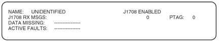
4-Line Disply, No Data Missing

15-Line Display, No Data Missing
| Data Missing Field Value Definitions | |||
| Field Value |
Meaning | Associated PID |
Effect |
| 0 | Missing Road Speed (MPH) | 84 | Sensor TRACS is not receiving road speed from the ECM. |
| 1 | Missing engine Speed (RPM) | 190 | SensorTRACS is not receiving engine speed from the ECM. |
| 2 | Missing Total Distance | 245 | SensorTRACS is missing distance from the ECM. |
| 3 | Missing Total Engine Hours | 247 | Engine hour data will not be available. |
| 4 | Missing Total Fuel | 250 | SensorTRACS will not record fuel data. |
| 5 | Missing Throttle Position | 91 | Coasting will not be a factor in over-speed threshold. |
| 6 | Missing Ambient Temperature | 171 | Ambient temperature will not be available. |
| 7 | Missing Parking Brake Status | 70 | Parked Idle Fuel will not be available. |
| 8 | Missing PTO Status | 89 | PTOE data will not be available |
Critical Event Reporting (CER) System Verification
Please note:
- For more info on CER, please refer to the OmniTRACS CER Installation Guide (80-JA368-1 Rev. C)
- OmniTRACS Supports Hardbraking, LDW & Roll Stability
- OmniExpress systems support HardBraking only
The Data Missing field on the screen below signifies certain types of critical events that are not supported on the vehicle (see table on the next page for details).
Warning:
- If “9” appears, then VDC event triggers are not supported and the customer should be notified (very important as this is the Roll Stability event trigger).
- If “A” appears, then LDW event triggers are not supported and the customer should be notified.
Refer to the display screens that follow when performing the system verification
Press the “C” key to access the CER status screen. The status screen shown below has VDC and LDW enabled
If the CER status screen does not display, call the NOC to have it enabled.
The various screen fields are described below:
| Field | Value |
| CER STATUS J1708 RX MSGS | The value should be a constantly increasing number when the engine is running. If the number is rapidly increasing, you are receiving J1708 messages. If the number is not rapidly increasing, you are not receiving J1708 messages and you need to recheck the installation. |
| DATA MISSING | Signifies certain types of critical events that are not supported on the vehicle. If “9” appears, then VDC event triggers are not supported. If an ”A” appears, then LDW event triggers are not supported. |
| HB | Hard brake is enabled/disabled. |
| S | Speed at which mobile unit detects hard brake events. |
| D | The rate of deceleration that triggers a hard brake event (Default = 9MPH/SEC). |
| VDC | Stability control is enabled/disabled. |
| S | Speed at which mobile unit detects VDC messages. |
| ON | Number of ATC (PID 151) “on” messages that must be seen in a row before a VDC event is considered to be in progress. |
| OFF | Number of ATC (PID 151) “off” messages that must be seen in a row before a VDC event is considered to have ended. |
| BIT | Setting that determines which bits the mobile unit tracks to detect VDC events. 0 = track brake bits only 1 = track engine bits only 2 = track brake or engine bits 3 = track brake and engine bits Default = 2 |
| LDW L/R | Left/right lane departure enabled/disabled. |
| S | Speed at which mobile unit detects LDW L/R messaged. |
Note: The E2 version of the Meritor-WABCO Braking System does NOT support Roll Stability…only versions E4 and above will. If the truck has the E2 version of HW for it's braking system, a "9" will appear in the Data Missing field above.
Basic Troubleshooting:
If the verification shows there is no data being received, check the following:
- Power and Ground Connections. Make sure the unit has 12-Volts on the Ignition line when the ignition is on and there is good contact to ground.
- Make sure there is a fuse in the fuse holder and check it with an ohm meter to verify that the fuse is good.
- Double check all spliced connections to the vehicle’s J1939 bus and to the OmniTRACS/OmniExpress’s J1708 wires to make sure there is good contact on all 4 wires.
If there is data available in some fields, (indicated by a “-“) and data missing in others, (indicated by a number) the Gateway Module is functioning correctly but there are some data items not available from the J1939 bus on this vehicle. No further troubleshooting of the converter is necessary in this situation.
Additional Information:
For additional installation and troubleshooting information refer to the Documentation Section at http://qc.diagsys.com
For product orders or return information is also available at the above web site.
Technical Support is also available by email at support@dsa-us.com or by calling:
(866) 296-8612 between the hours of 9:00 and 5:00 Eastern Time (US).
| Attachment | Size |
|---|---|
| QualcommInstallGuide11.pdf | 360.08 KB |